Homemade GPU rendering realistic scenes in real time, for some definition of "GPU," "realistic," "real time," and "homemade."
In my introductory Digital Systems class (Duke ECE 350), we made a basic 5-stage pipelined processor in Verilog. For the final class project, I added graphics capabilities to my CPU with a GPU featuring a 16-lane half-precision vector processor reaching 400 MFLOPS of throughput. Video is output through the built-in VGA port of the Nexys A7 FPGA development board.
This page describes some of the features and interesting design decisions that went into this; for a more complete description, see the technical report I wrote for the class as well as a video demo.
Features thirteen 20-bit instructions with nonsensical binary encoding decisions. Includes instructions like "decrement the X register and branch if the new value is nonnegative" and "compute 1/pi times arctan(x)" while omitting useless garbage like "add immediate" and the ability to write to registers 0-16.
Apple claims their unified-memory architecture allows lower latency and higher power efficiency, but what could be faster or more efficient than getting rid of memory entirely? Want to communicate between CPU and GPU anyway for a laugh? We have a tool for that: it's called REGISTERS.
Ok, that last point was a bit of a lie: the GPU does have a framebuffer to store the rendered image. In fact, this framebuffer (along with some other memories) uses 97% of our FPGA's available BRAM. Details of my struggle to fit this in are in Section IV.A of the techincal report linked above.
The GPU core has a 4 stage (Fetch, Decode, Execute, Writeback) vector pipeline, with 16 lanes. Of the 8 arithmetic operations supported, 5 are implemented with Vivado's Floating Point IP blocks, the 2 simplest (floor and abs) are implemented manually, and 1 (arctan divided by pi) uses a 2048-entry lookup table.
A simple wrapper/scheduler module runs the program once for each block of 16 pixels (left-to-right), setting registers for the x and y coordinates for use in the program. Once the program reaches a special "done" instruction, the resulting color (placed in 3 specail registers) is written to the framebuffer. A separate VGA output module scans through this framebuffer and outputs at 60fps, with no VSync or tearing mitigation to speak of.
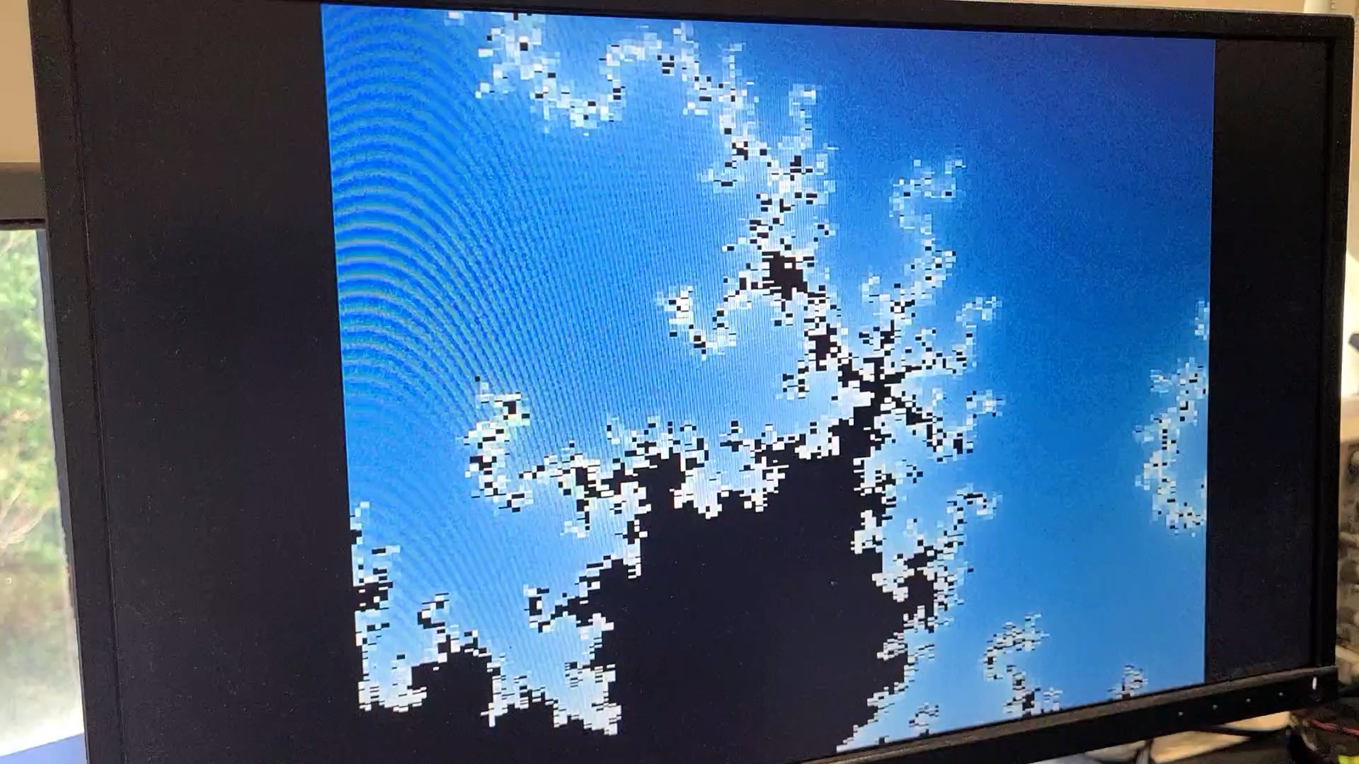
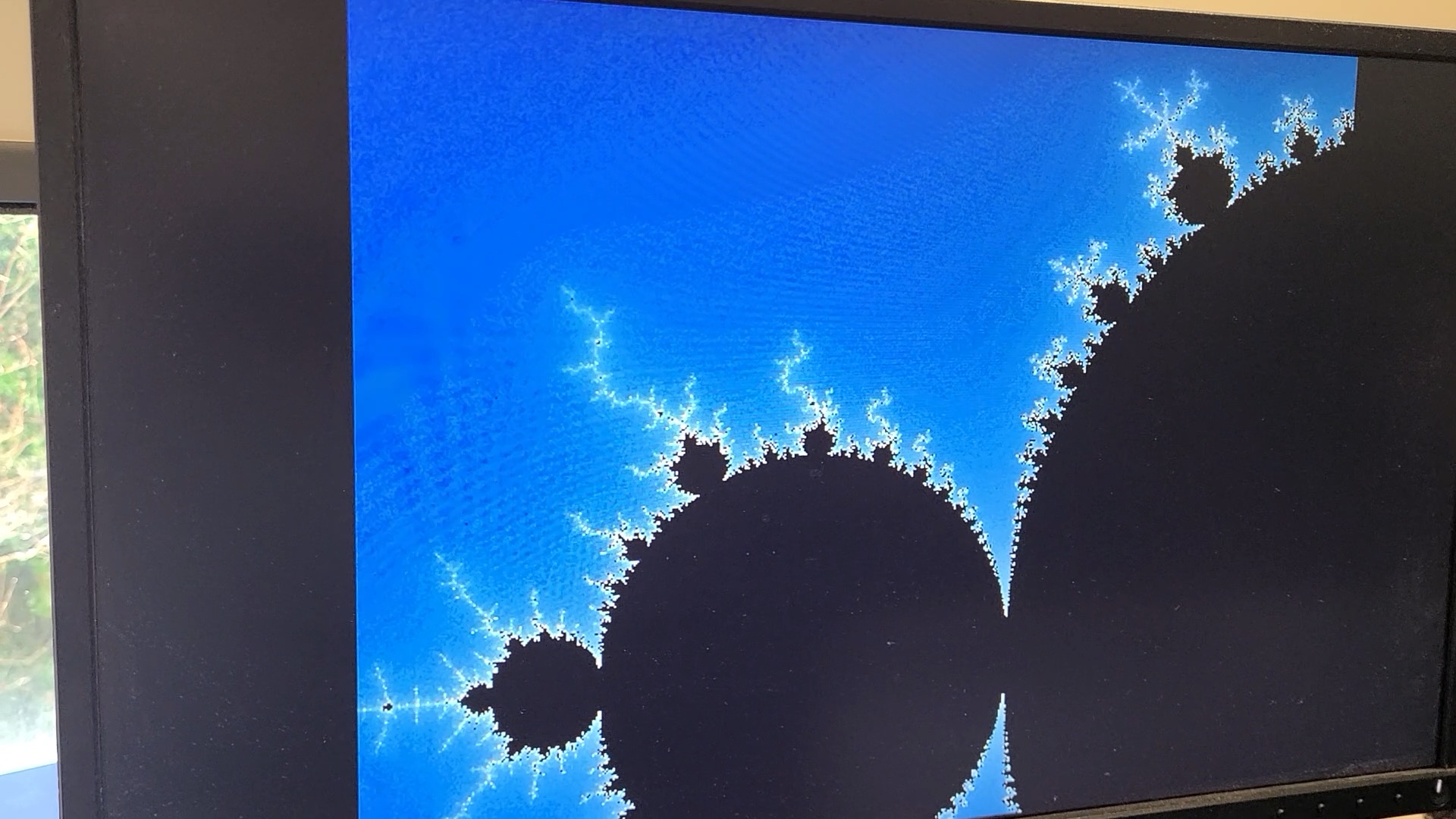
All operations use 16-bit (half-precision) floats, which becomes all too apparent after zooming in only a few times on my Mandelbrot visualizer.
Because 16-wide memory access is not a problem I wanted to think about for a 3-week class project (I don't even have integer registers to store addresses), I decided to use 32 registers for all communication from the CPU to GPU as well as for all computation.
For simplicity, the first 16 registers each store a single scalar value and are read-only to the GPU core. 3 are special cases (zero register and x and y coordinate) and the remaining 13 are used for any parameters set by the CPU and constants used by the GPU (to avoid wasting cycles setting constants repeatedly). This ended up being very nice for debugging, as the output image is (eventually, barring reads of leftover values in registers 17-31) a pure function of these registers, allowing easy testing of GPU programs before doing any integration with the CPU.
The remaining 16 registers are vector registers (with a separate register file in each element's datapath). Register 16 holds the numbers 0-15 (each element's index), providing the only source of divergence between vector elements. The rest are standard writable registers, with 3 being reserved for the pixel's output color.
After a program is done running on a pixel, the resulting floating-point color values (clamped to 0-1) need to be converted to integers for the VGA output. Unfortunately, the Nexys A7's VGA interface supports only 4 bits per channel, which initially led to severe banding.
To remedy this, I introduced randomized dithering to the float-to-fixed conversion. Values are converted to 7-bit fixed-point first (now ranging from 0 to 15.875), and are rounded up or down based on a pseudo-random per-channel cutoff generated with an LSFR. This ensures that the expected brightness of a subpixel precisely matches the output value (to 7 bits, anyway), despite only having 4 bits to work with.
For slower renders like the ball demo shown, recomputing this dithering per 60fps VGA frame would have been preferable, but BRAM limitations meant that 12 bits per pixel was the maximum possible in the framebuffer, even if more were supported by the VGA interface.
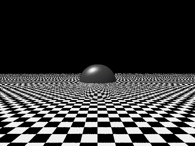
My 3D scene without dithering, with significant banding.
Adding dithering significantly improves the quality, despite having only 12-bit color.
Initially, my GPU was purely a vector machine, with every instruction running on all elements. Anything resembling conditional control flow was implemented with a simple conditional move instruction, effectively executing both branch paths and selecting the correct one.
Later on, however, I decided to basic support conditional branching, with significant restrictions. When the single supported branch is encountered, any elements taking the branch set a "next PC" register to the branch destination and do not execute instructions prior to this point being reached. If some elements of the vector do not take the branch, this is equivalent to predication-based control flow, but if they all eventually do, the fetch stage includes logic to skip ahead to the minimum of these next PC registers.
This logic can significantly simplify code (although it was a bit too late to do much in that regard) and also improve performance, which it did greatly. The ability to break out of a raymarching or fractal computing loop early improved the raymarched 3D scene's performance from 3-4 FPS up to 8-10 FPS. While it's not a true SIMT processor (for many reasons; we don't even have memory!), this optimization was one of my favorite ideas that went into this project.
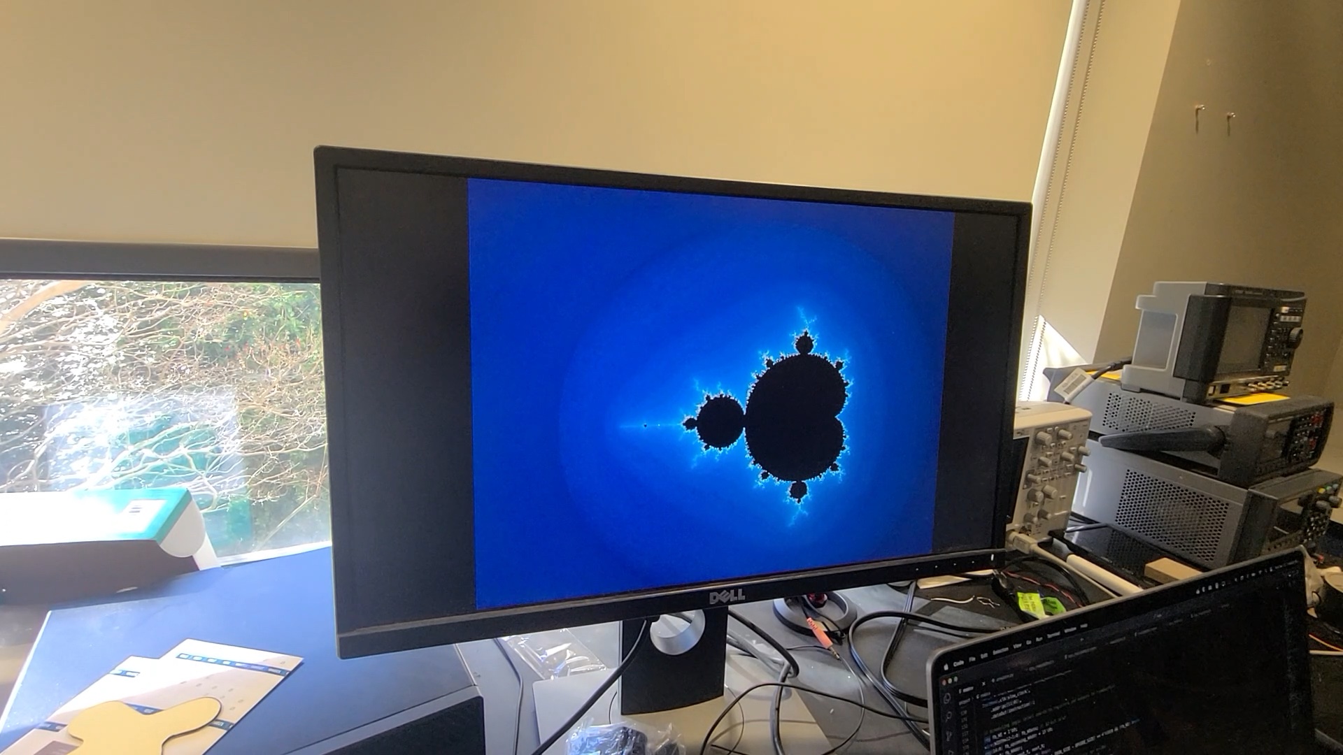
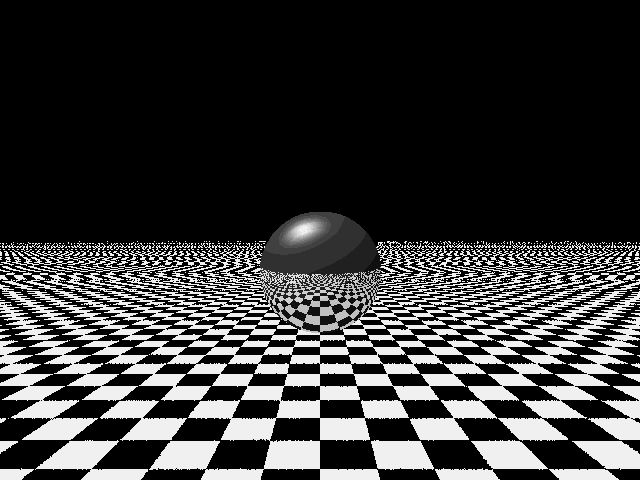
To show off the GPU, I wrote three small demonstration programs, showcased in this short video of part of my final presentation. These demos included: an "auto runner"–style game rendering a 2.5D tunnel in real time and responding to input, a raymarched 3D scene of a ball on a checkerboard with Phong lighting and reflections, and a fractal explorer showing the Mandelbrot set.
The code for these demos, as well as the GPU (but not any Vivado IP blocks or CPU components required to use it) can be found on GitHub. Additionally, I hope to make a few posts about other small interesting aspects of this project, and will link them here if I ever get around to it. Below are a few photos of the demos:
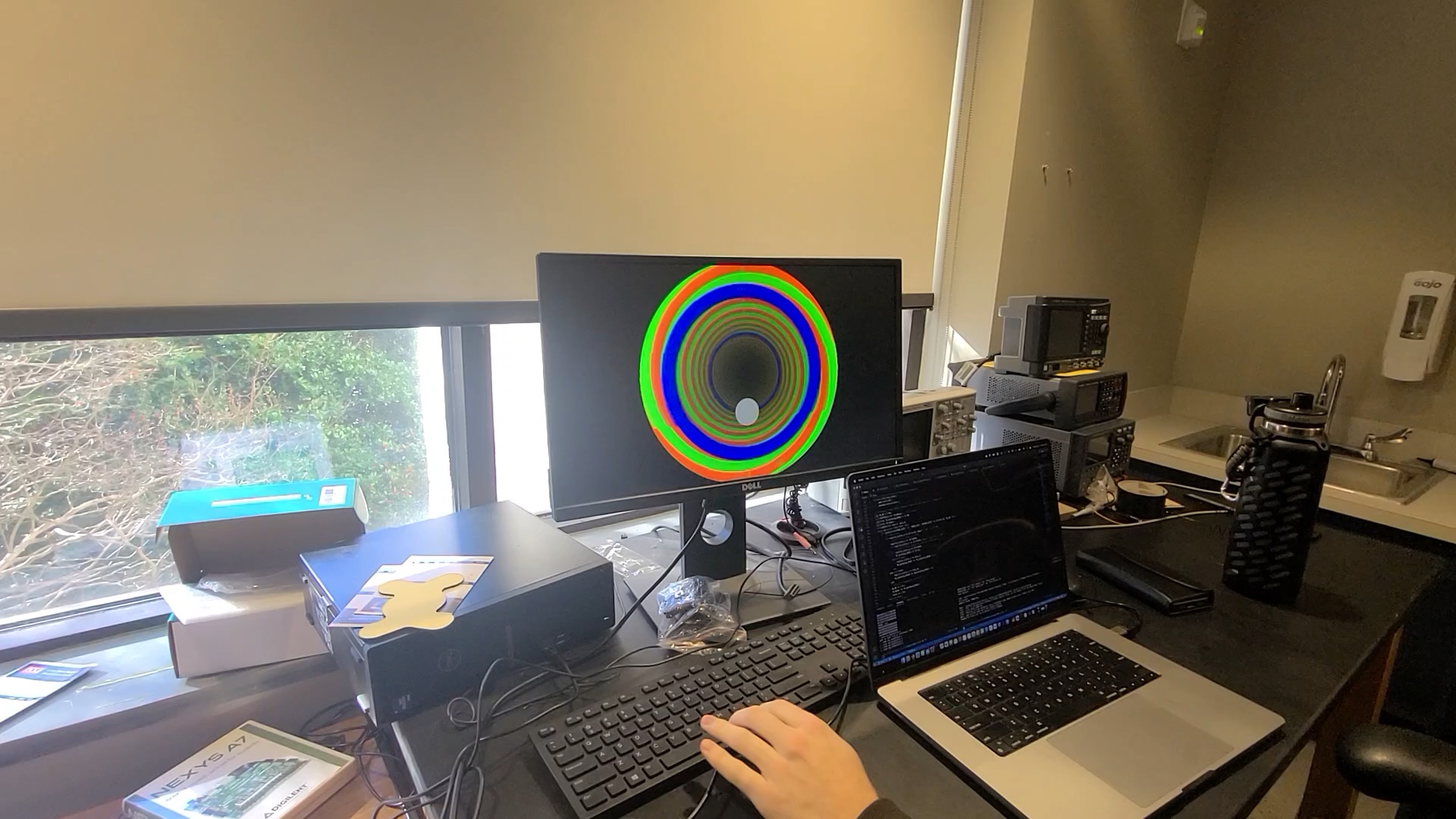
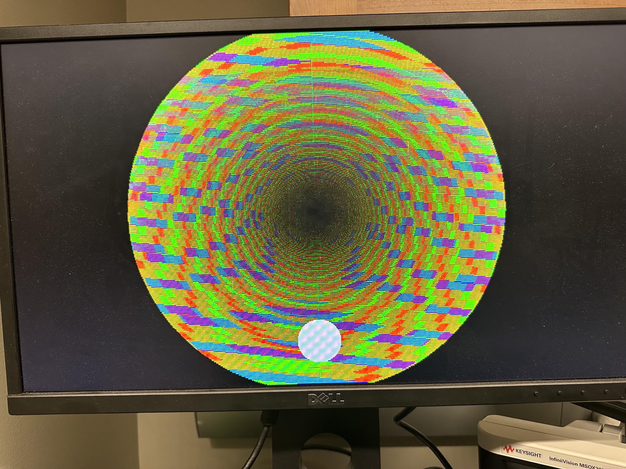
The demo game as I jump over a blue ring. The red/green tunnel is rendered with basic trig, with shading based on the calculated distance to the tunnel giving a 3D effect with little computation.
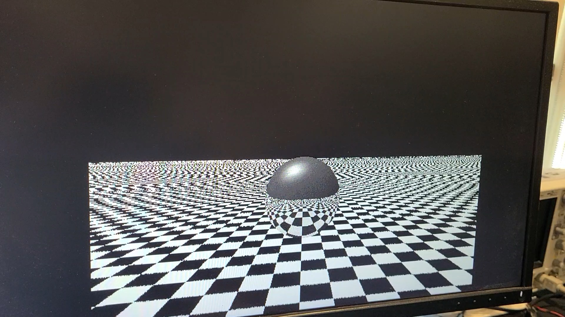
The raymarched 3D scene, featuring a reflective ball on a checkerboard floor. Could use some antialiasing and less ambient light on the ball, but not too bad.
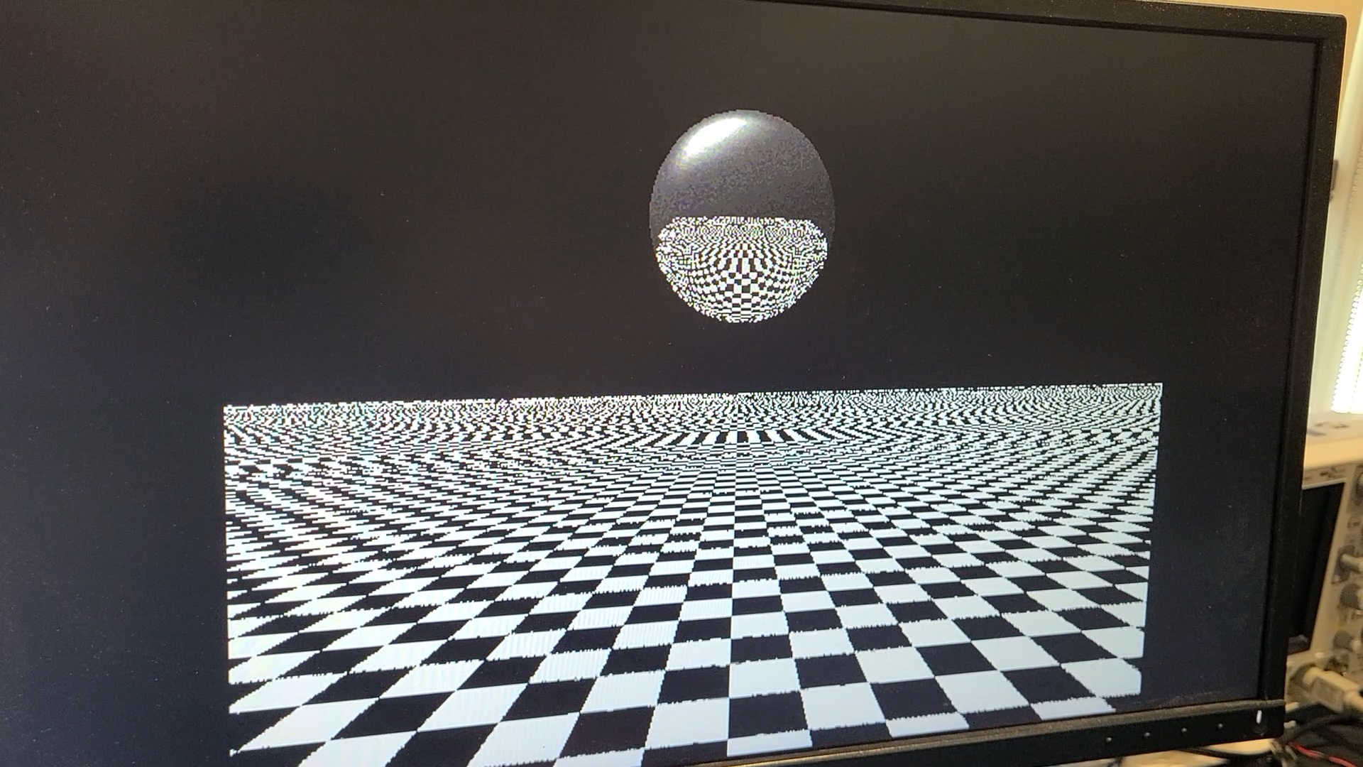
The CPU program bounces the ball up and down. At its highest, aliasing makes reflections pretty inaccurate, but it's less noticeable in motion.
My rendering of the Mandelbrot set. A lack of logarithm instruction makes smoothing iteration count hard, but square rooting the blue component to get green and red gave a suprisingly nice color scheme!
Zooming in on the Mandelbrot set. Imprecisions in floats and low resolution make this not much of a fractal, but not too bad at low zoom.
An earlier version of the demo game had no loss condition and sped up infinitely, leading to an interesting visualization of rolling shutter–like effects after running for an hour.
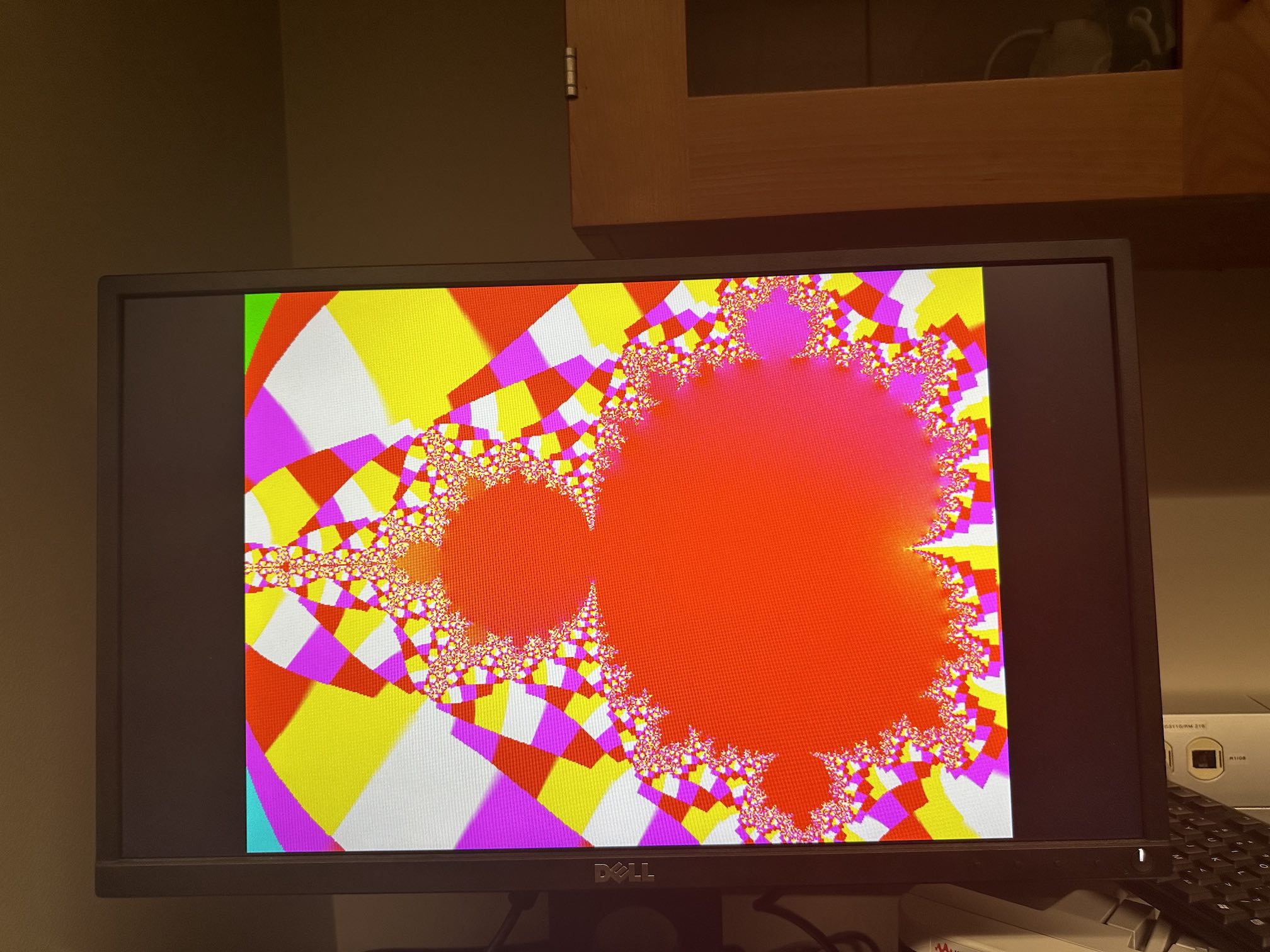
An early test of the Mandlebrot explorer just output the real/imaginary coordinates of the final point reached on the green and blue channels, leading to an interesting color scheme (note that colors are assumed to be 0 to 1, which most coordinates are well outside of, leading to discrete tiles).