Garmin Testing Device

Underwater testing device for Garmin dive watches and air tank sensors, controlled automatically using a web app.

Overview

Garmin's Sonar Engineering Team creates several dive watches and air tank sensors designed to communicate with each other using their SubWave Sonar technology while underwater. Until recently, to test and calibrate these precise devices, Garmin attached them to a boat using 12 ft PVC poles, leading to several feet of deflection during testing and decreasing both accuracy and repeatability of results.

To make the testing and calibration process more stable, accurate, and consistent, I worked with a team of engineers in my EGR 102 class to design and build a new mounting system that would hold the dive watches and air tank sensors fixed in position underwater, while being controllable using a web app to set the exact depth and angular position of the devices being tested.

As electrical team lead, I personally designed the mechatronic control system, from the motors used to physically move the testing rig to the UX of the web app used by engineers while performing tests, as well as all the microcontrollers and firmware in between.
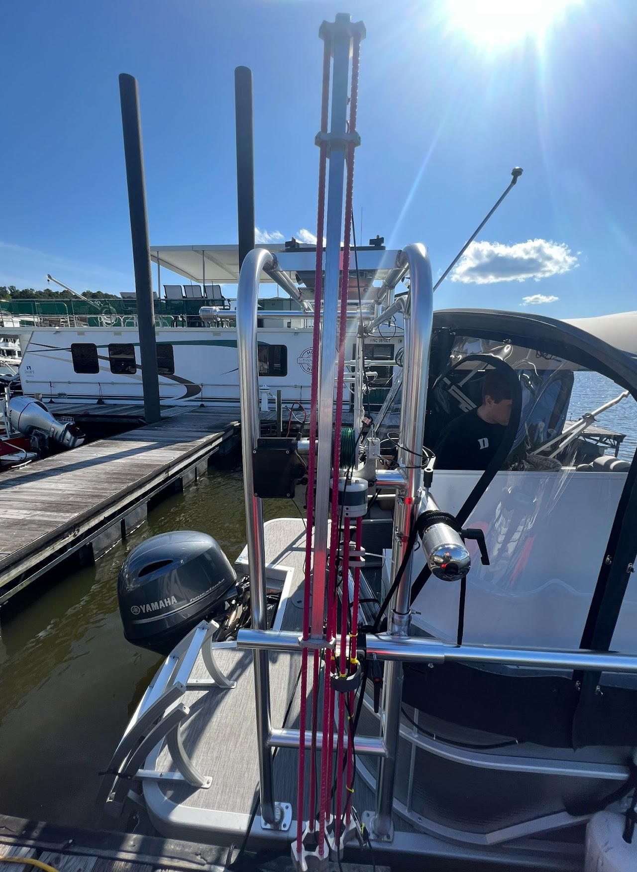
A long pole-shaped device, made of aluminum and fiberglass rebar, mounted to the side of a boat.

The new testing system installed on the boat.
Design Goals

Accuracy

Control system must move devices to within 2" of the desired depth and 5° of the desired angle, withstanding forces from the weight of the device and underwater currents

Durability

The testing system will be stored outdoors on a boat and be operated underwater, but still must be built to last without significant maintainance.

Usability

Several test engineers will work with the system, so it should be fairly easy to use and understand, working with the engineers' goals and workflow rather than against them. In addition to human usability, it should also be easy to extend and integrate with current or future autonomous testing workflows.

Physical Design

While I can't take too much credit for the design or manufacturing of the testing rig's mechanical structure, making it move required designing a robust depth and rotation control system, as well as selecting motors that had the necessary power and precision.

For the depth adjustment, we used a winch-like system with a motorized spool lifting the tested device up and down on a telescoping pole, while rotation was achieved by rotating the entire testing rig using a motorized belt. This was done to avoid placing any electronics underwater while maintaining full control over the device's position.

For motors, we eventually chose small, high-gear-ratio DC motors (this one, in particular) with quadrature encoders to provide the necessary torque while remaining power-efficient, small, and inexpensive.

To drive these motors, we used the L298N H-Bridge motor driver, mostly because it was most conveniently available. This ended up being a significant mistake, with the L298N frequently overheating and causing problems; if you are working on a similar project, I'd highly recommend researching a better driver.

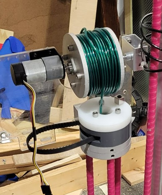
A small motor driving an alumninum spool with coated steel wire wrapped around it. The motor and spool are mounted to a mounting plate, and the wire continues downward through the testing device.

The depth control mechanism, including the winch system used to adjust depth and the DC motor with encoder powering it.

Wired Control

Because we selected simple DC motors with encoders, achieving the precise position needed required implementing some sort of control system. While the ESP-IDF framework provides a PID component, I implemented mine manually on top of the ESP-IDF PWM and pulse-count functionality, which was fairly simple to do.

This ended up being very beneficial as we began testing with the entire assembly, as I ended up needing to add a decent amount of custom control logic beyond the basic assembly.This included functionality to recognize when the motor was stalling (somewhat common in early rotation testing), recognize when friction (and gearing) was sufficient to hold the spool in place without applying power, and move to specific angles efficiently by accounting for full rotations.

Wireless Control

The ideal testing workflow we were focused on providing involved controlling all testing via a laptop in an intuitive, hassle-free way. We achieved this with a fairly basic web app, served by the ESP32 that also controlled the motors themselves.

The primary testing rig's controller acted as an access point, providing a WiFi network that a laptop could connect to. It then served both the web app (created using PicoCSS, which I highly recommend) as well as a fairly basic API allowing for the depth and angle to be set, as well as the current position to be read. This makes the system very extensible, with any new systems able to integrate easily into the current API.

Because two testing rigs needed to be controlled simultaneously when testing communication between two devices, the secondary one acted in station mode, connecting to the predefined WiFi network created by the primary AP rig. The station mode rig polled the primary rig periodically for updated depth position targets, matching its own position upon observing any changes.

Calibration

Given the amount of effort put into the system's precision, accuracy was obviously a large concern. For depth accuracy, a simple startup calibration routine was sufficient, raising the rig to its known minimum depth as detected by the end of the motor's travel.

Rotation accuracy was a trickier problem, especially because verifying the device's current rotation underwater was difficult. To solve this, we used a Hall Effect Sensor placed at the top of the testing rig, detecting a magnet on the rotation mechanism. At startup, at least 5 rotations are completed to define an absolute zero point, and this point is monitored as the user rotates the device.

During testing, both calibration systems exceeded requirements, with depth calibration varying less than 0.5" and rotation by less than 2°.

Productionizing

After a few months of brainstorming, design, implementation, and testing, the end-of-semester deadline was approaching faster than expected. While we were now confident in our design, nearly every part of it was not ready for production use, from the 3D-printed PLA spool holding up the device to the mess of jumper wires connecting everything.

While the rest of the team spent hours machining the final product, I worked on my first-ever PCB design to fit the electronics into the waterproof casing on the device. Using the soon-to-be cancelled Autodesk EAGLE software, I layed out the board, including making a basic custom package for the H-Bridge mounting holes.

After one failed iteration (due to downloading the wrong ESP32 module and later having to patch it) and some simple soldering, we had our working PCB. Once we wired a power cable for interfacing with the boat's onboard 12V supply, the electronics — along with the rest of the device — could be installed on the boat and used for future Garmin testing.

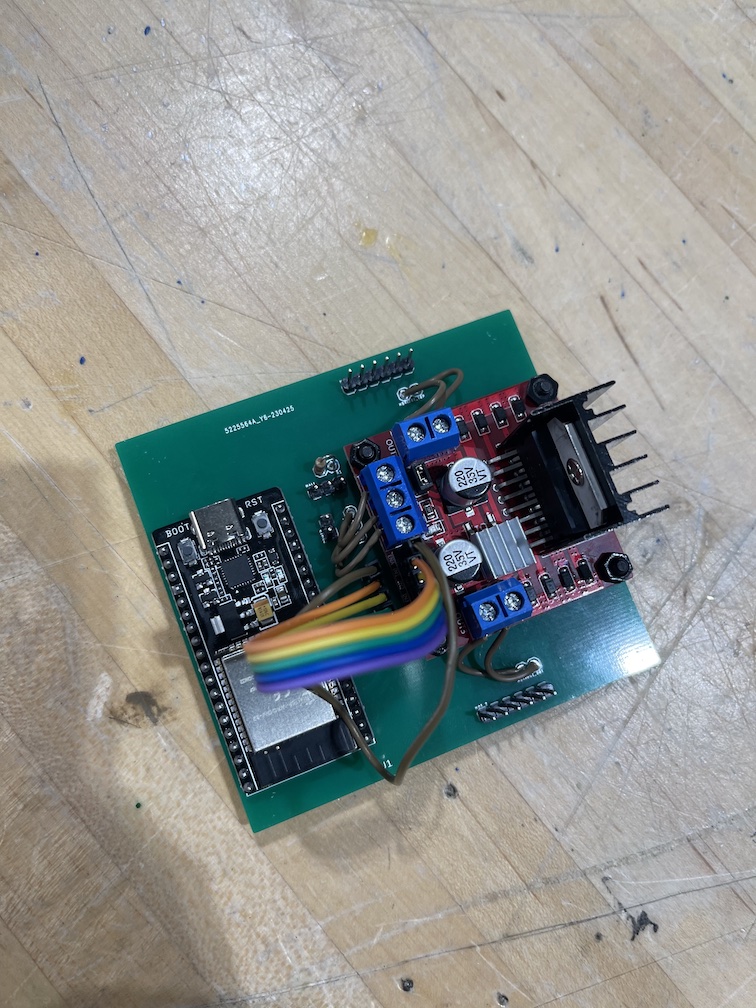
A small PCB with through-holes for a microcontroller, several pin headers, and some resistors, as well as four mounting holes for the motor driver.

The final PCB design, made incredibly simple by the (admittedly poor) choice of motor driver, which had to be connected using jumper cables.

Final Thoughts

This felt like my first "real" engineering project, with an actual client and team who were relying on me getting things done. While there is so much I would do differently if I could go back, overall it was a success, and I learned so much throughout the process. Here's some other pictures from the project:

A small PCB with an ESP32 microcontroller and H-Bridge motor driver attached, along with several jumpers connecting the H-Bridge to the PCB.

The assembled PCB, with jumper cables attaching the screw terminals on the H-Bridge to the board. The 6-pin headers on top and bottom plug into the motors.

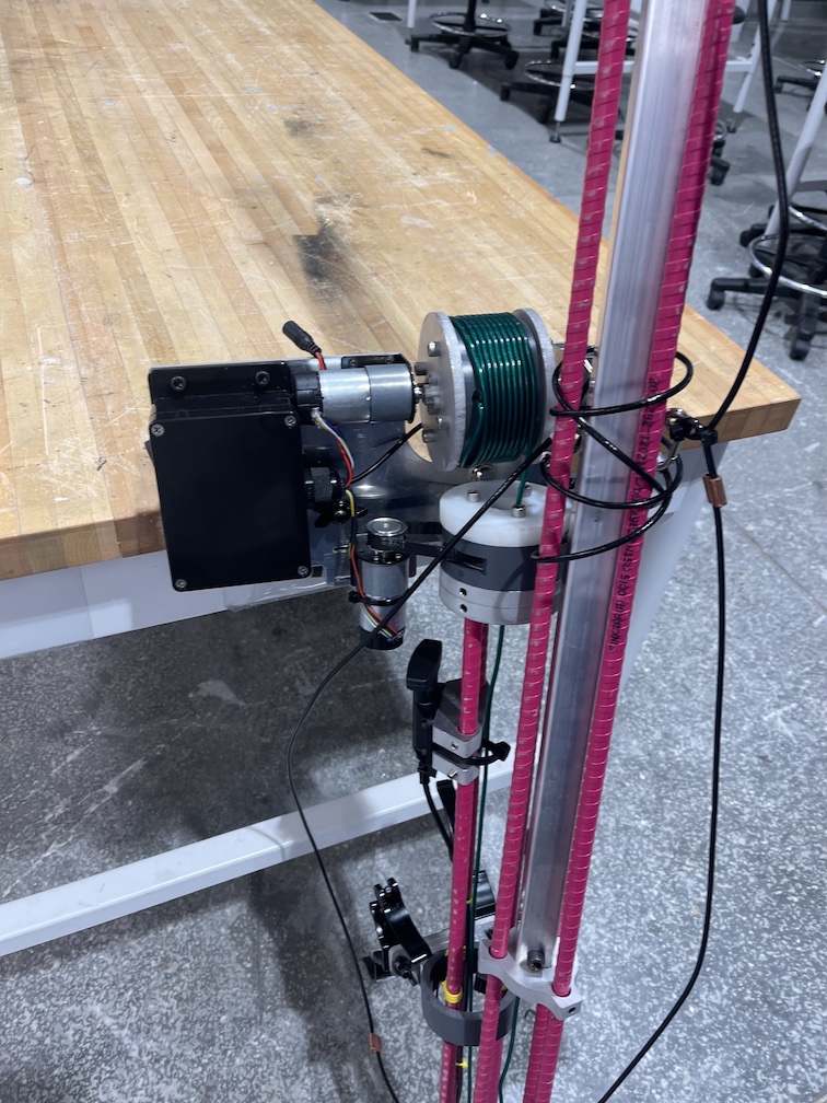
The complete device leaned against a table, cropped to the electronics on the mounting plate in a closed waterproof box.

The main testing device all ready for delivery.

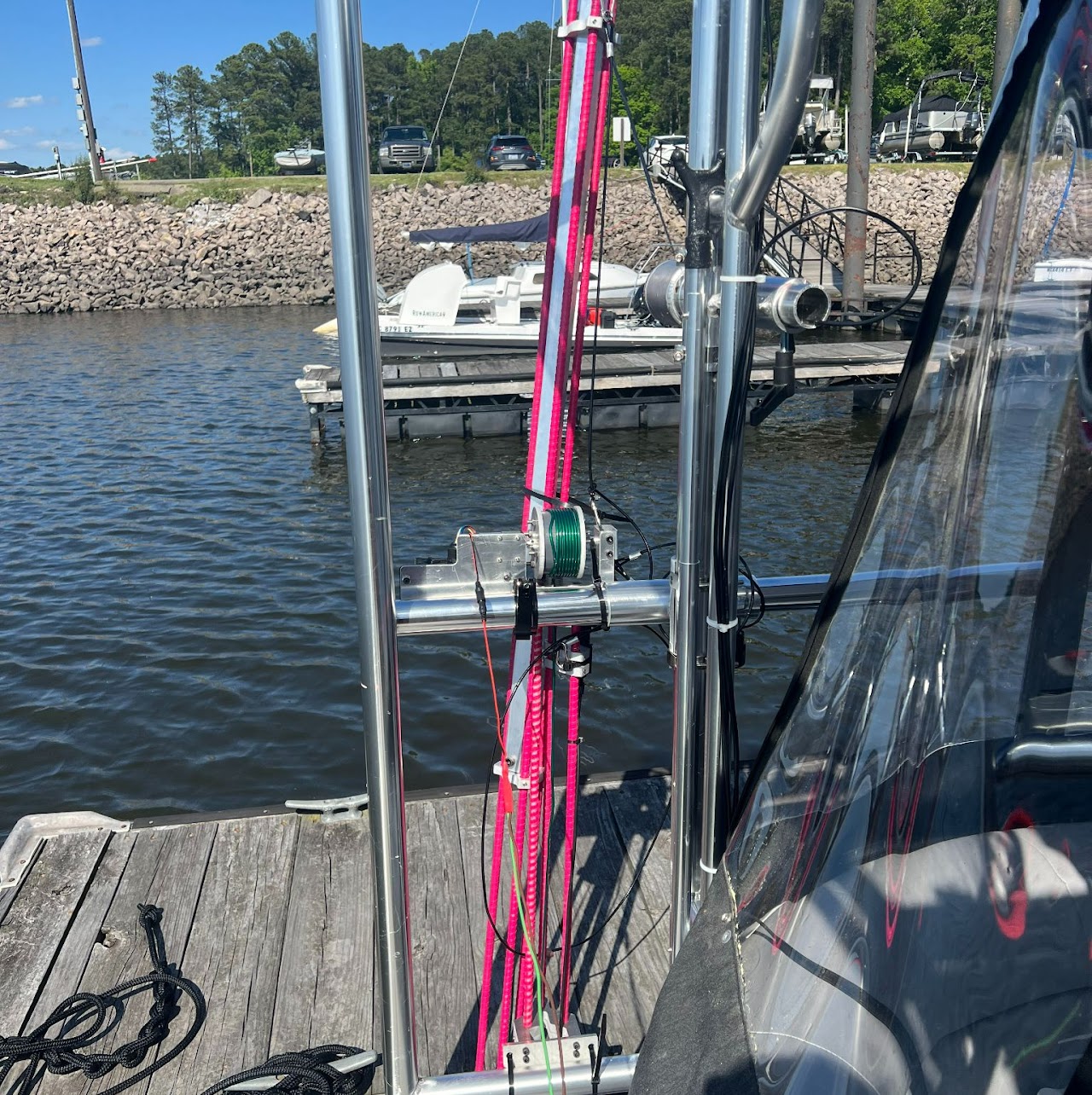
At a lake, on a docked boat, the testing device sits attached to metal rails running along the side of the boat.

The secondary (non-rotating) device mounted to the boat's railing for testing.

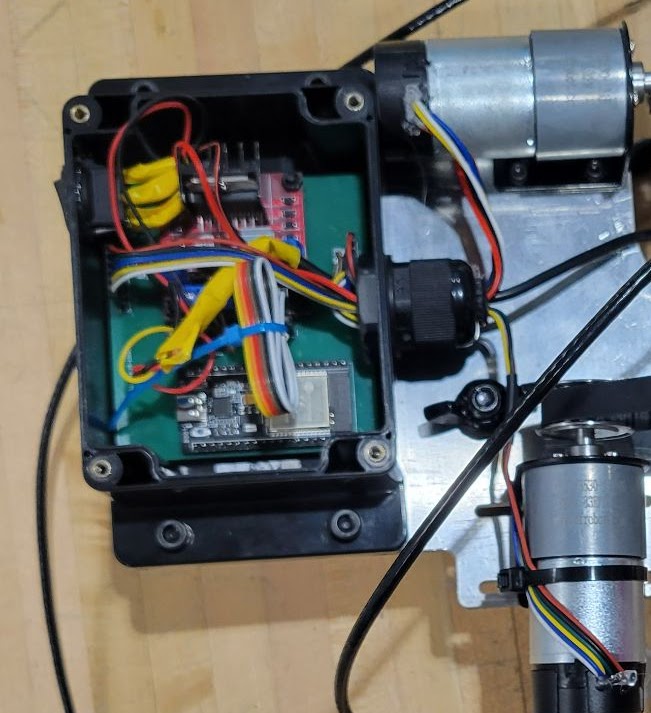
A small waterproof box attached to the metal mounting plate, containing a PCB, microcontroller, motor driver, and several wires connecting everything.

The complete electronic system for the primary testing rig, all installed on the PCB and stuffed into the waterproof casing.

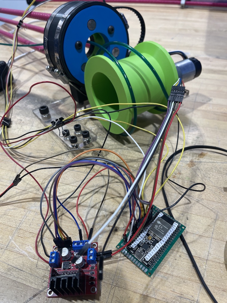
A large number of long wires connecting an H-Bridge motor driver, an ESP32 attached to a protoboard, and an early 3D-printed prototype of the rotation and depth adjustment mechanisms.

The complete mess of wires I was working with for the first 85% of the project. What was I thinking?

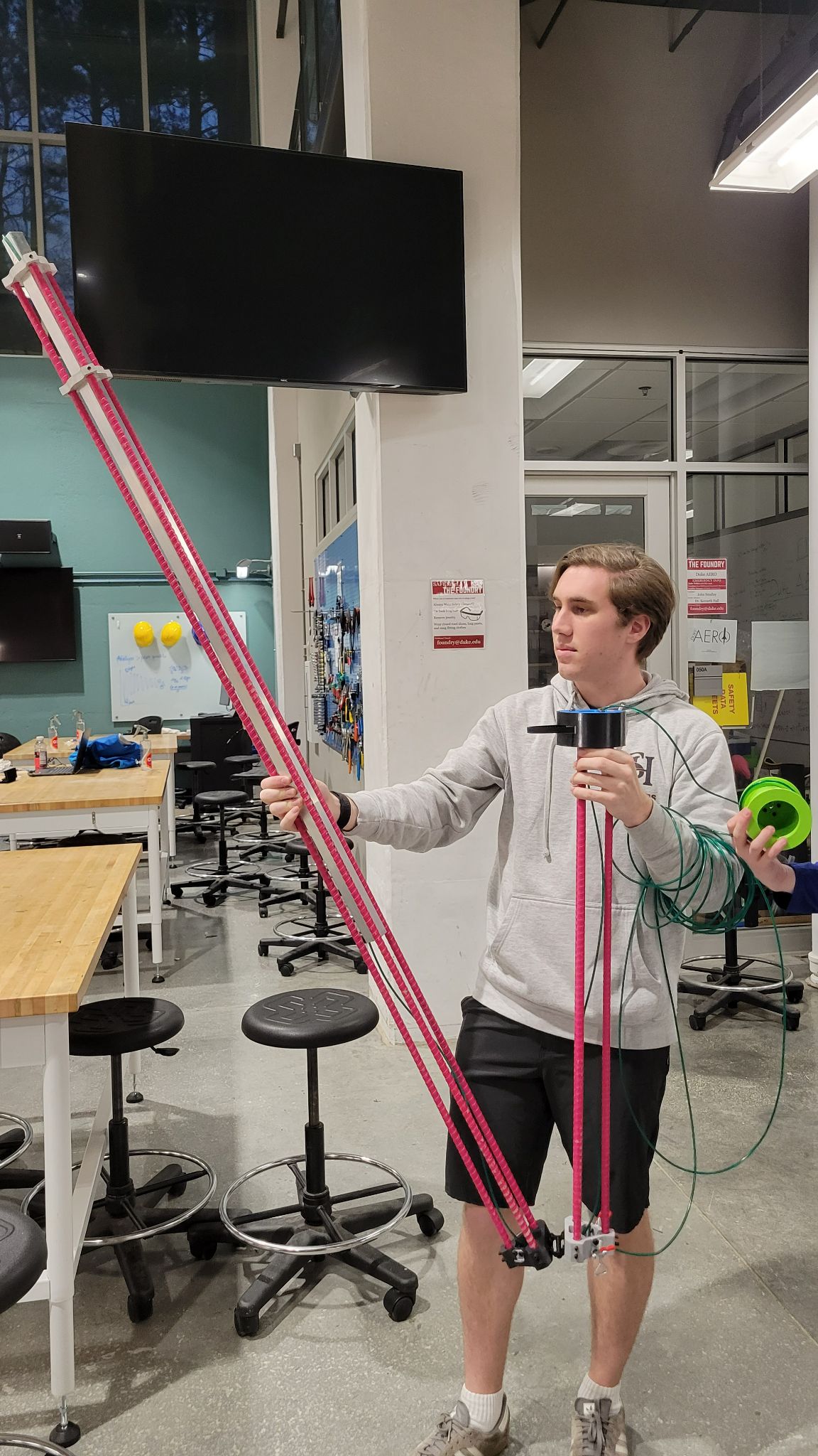
Me holding the long fiberglass rebar of testing device in an incomplete state, currently unfolding it to test the hinge.

The best picture I could find of me with the testing rig, taken pretty early into the design process while working on the folding mechanism.