Phase-Locked Loops, Part 2: Phase Detection
2024-04-26
This post is part of a series on Phase Locked Loops (PLLs).
The purpose of a PLL is to adjust an output signal's frequency to match that of an input. To do this, it must be able to measure the difference in these frequencies, detecting whether the current output (or some function of it) is ahead or behind the input. To do this, we employ a phase detector.
There are a few types of phase detectors, varying in what the inputs and output look like. On the input side, we'll limit ourselves to digital phase detectors. On the output side, most phase detector circuits produce one pulse on every cycle of the inputs, with the length of the pulse (and therefore average voltage) proportional to the phase difference. This signal will be converted to a stable analog voltage in the next post.
If the inputs are perfect clock signals (50% duty cycle), there's a very simple digital circuit that can detect phase differences: an XOR gate. When the two inputs are perfectly in phase, the XOR is a constant 0, and as they differ in phase, brief pulses of 1 are output, up to a constant 1 when the inputs are perfectly out of phase. However, there's still one thing missing—how can we tell which signal is ahead/behind the other if our XOR only detects when they differ?
To fix this, we can simply shift what we consider “in sync,” using our phase detector to measure how far from 90 degrees out of phase the signals are, rather than how far from in phase they are. In other words, we consider a phase detector output of 50% duty cycle to be 0, giving us room to detect and distinguish differences in both directions. For the PLL as a whole, this moves the “lock point” we try to reach from perfect synchronization to one signal being 90 degrees ahead the other.
More mathematically, we can represent a phase detector as a function from phase difference (ranging from -π to π) to some output (cycle averaged) voltage. For the XOR phase detector on perfect square waves, this function is f(x) = abs(x) / PI, with output ranging from 0 to 1. For our PLL's feedback loop to result in a stable equilibrium, we want this output to be approximately linear near the target lock point, responding like a restoring force to any phase difference. Clearly x = 0 is a poor choice of stable point for this function (the derivative is undefined), but x = PI/2 is very good, as it maximizes the linear feedback region of our phase detector.
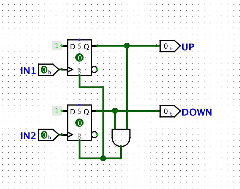
Of course, even with this lock point adjustment, there are some properties of the XOR phase detector that make it less than ideal in practice. For example, variance in duty cycle of the inputs significantly affects the XOR phase detector's performance. To avoid this, we can use flip-flop based designs, where the edge of the signals is detected, rather than the level. Consider the following circuit made up of two D-flip-flops in a somewhat unusual configuration:

This is called a Phase Frequency Detector (PFD), and it fixes many of the issues with the XOR circuit (and other simple designs). From the initial off state, any input rising edge will be latched in the UP or DOWN output. Once the other input rises, the other output being latched will immediately (asynchronously) reset both flip-flops. So, the output is high for the time between the leading and trailing inputs rising, giving a measurement of the phase difference between them. Depending on which input is ahead, either the UP or DOWN output will be on, signalling which direction the output frequency should be adjusted.
Unlike the XOR circuit, the PFD is not sensitive to duty cycle variance, locks to zero phase difference (enabled by separate outputs for each direction of phase difference), and performs well when one frequency is very far from (even several times) another. There are still a few problems, such as very short output pulses when the input phases are close, resulting in a deadzone, as well as some timing issues with the reset, but these (and other optimizations) are a bit too advanced for me to bother with here.
This concludes (for now) my exploration of phase detection for PLLs. Next time, we'll look at the filter that converts the phase detector outputs to a more useful control signal.